
Article Ref – ART187
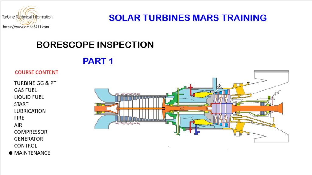
This presentation is going to review the borescope procedure for the Mars turbine.
It is limited to a standard borescope inspection. From time to time issues will arise due to changes in the manufacturing process, design change in materials, parts upgrade etc. You would expect that a turbine would have all its issues resolved after a couple of years in production, but there will always be some issues.
The end users are often unaware of issues, but they will be known to the Solar Field Service. They are privy to this information which normally comes in the form of a Tech Letter (for Solar personnel only).
If Solar does share information with a customer it will be by means of a Service Bulletin.
A borescope inspection can be very intimidating for new technicians, but if you master the basics, you will be able to carry out a borescope inspection on any turbine, given some minor additional training.
A cross section of the turbine is very important to have at hand. You need to know what to expect when you insert the borescope in the turbine. It is also invaluable when you have to navigate inside the turbine.
It is important not to get too ambitious trying to get into places that you might get your borescope stuck. Not only will you face an expensive repair of the borescope, the turbine may very well have to go back to Solar for disassembly.
The borescope inspection is normally carried out every 4,000 hours, but may have to be done more frequent if damage is found.
At the other end of the scale, some operators accumulate very little hours in service and may take years to accumulate 4000 hours. In a situation like this it is necessary to do a partial borescope once a year. The internal part of the turbine may corrode, especially in a salt laden atmosphere.
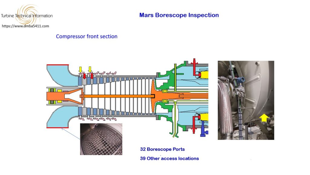
Compressor front section.
The Mars has 32 borescope ports, and 39 other inspection locations. It was designed with sufficient ports to allow a complete inspection of the internal parts.
Starting at the front of the turbine, an access panel on either side of the air intake is removed to reveal a protective mesh, that prevents foreign objects entering the turbine. Remove this mesh for easy access for your borescope.
Entering from the front of the turbine gives you access to the first and second stage rotor blades, plus the IGV and First Stage VGV.
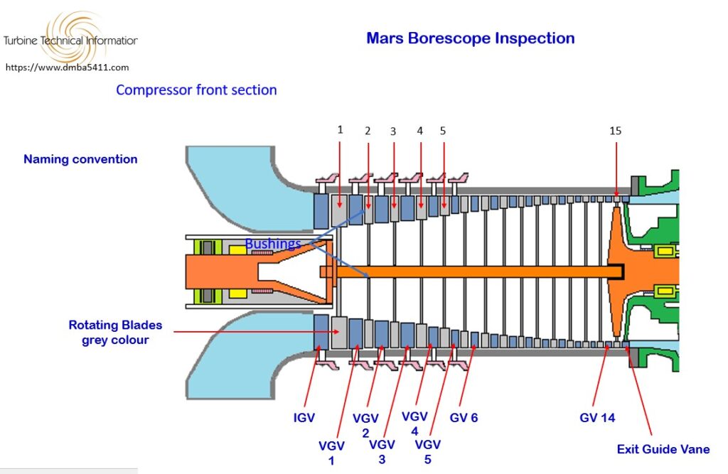
Let us talk a little about the naming convention for the compressor staging as it can be confusing.
Here we have the rotating blades. This is the first stage, second stage, third, fourth, fifth all the way back to the fifteenth stage. This part is straight forward.
There is however some cofusion when we get to the non rotating stator blades.
The first stage is the Inlet Guide Vanes (know as IGV). As the air comes in from the air intake the first non rotating blades it will come across are the inlet guide vanes.
The second stage of non rotating blades are called the First Stage VGV (variable guide vanes).
The next stage of vanes is the second stage etc. This can be confusing and it would have made more sence to name the IGV – First Stage Vane, and to call the First Stage VGV the Secod Stage Vane etc.
But this is the system we have, so be careful when making out borescope reports or interpreting the reports of other people, that you use the correct name which ensures the person interpreting the report is thinking about the same location.
Moving back along we have the third stage VGV, fourth stage VGV and fifty stage VGV. This is the last stage of variable blades.
The next stage back is the 6 stage Guide Vane.
All the way back to the 14 stage Guide Vane.
and the very last one is the Exit Guide Vane.
This is what they are called and it is what you must use in your reports.
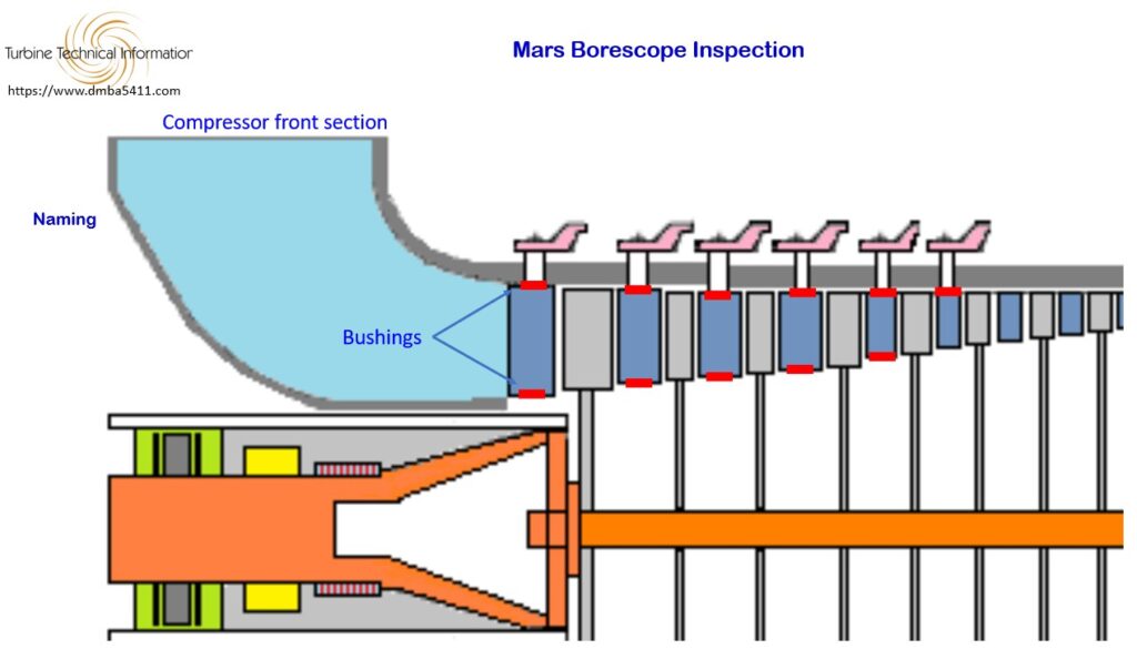
The next point to discuss are the bushings on the variable vanes – all six stages.
There are outer and inner bushings where the blades rotate on.
The sixth stage at the back does not have an inner bushing.
These bushings need to be evaluated during the borescope inspection to see if they are very dirty, or that there is a buildup of dirt, corrosion or deposits such as salt. These bushings can get so fouled up that they seize up causing the actuating leaver to deform and break.
An external inspection of the angle change mechanism should be carried out while borescoping.
This loss of control of the vanes can cause a local stall of the air and if serious enough can cause the turbine to surge.
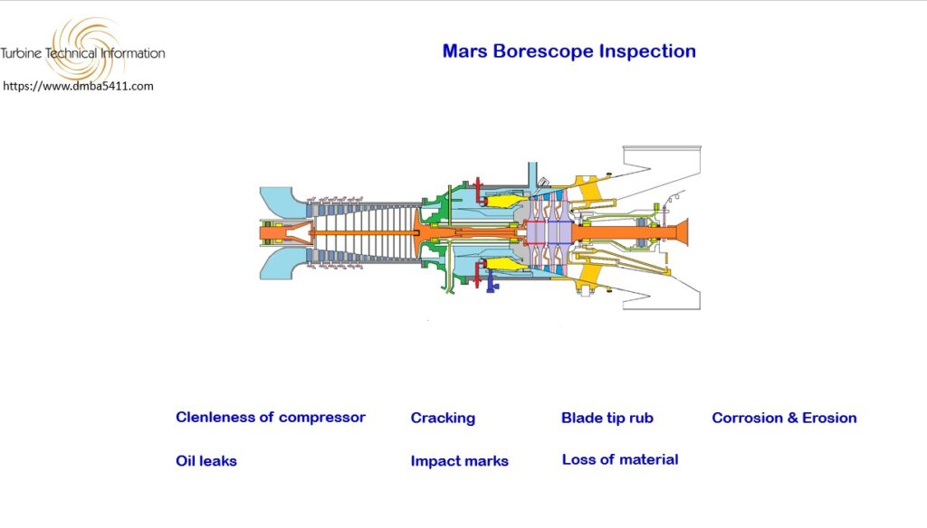
The following is what you need to look for during the borescope inspection of the compressor.
Note the condition of all stages of compressor and take photos which will be used in the report.
Look for clenleness of the compressor. This will give an indication of the effectivness of the air filtration system. It may alos be a guide to the interval you need to use between compressor washes.
Note any oil leaks. If the early stages of compressor are coated with oil and dirt sticking to the blades, it is most likely that number one bearing seal is not in good condition. If you see oil in the aft end of the compressor it is most likely the number two seal that is leaking.
Show the cross section and where the oil may leak out.
Each rotor blade needs to be inspected for cracks. No cracking is good but cracking at or near the blade root is of concern. The danger of the blade breaking away from the root is high. This would most likely totally destroy the turbine.
Look for any impact marks arising from items going through the compressor. It may be an indication of more serious damage further back along the turbine.
Look for any blade tip rubbing. Note an photograph any blades found with this damage. Normally this is not an issue as long as large pieces of material are not being liberated.
Loss of material due to cracking, impact. This need to be recorded and photographed.
Corrosion and errosion needs to be recorded and monitored. Sea atmosphere can be harsh on metal surfaces. And poor air filtering can see particles passing into the air stream and erroding blades.
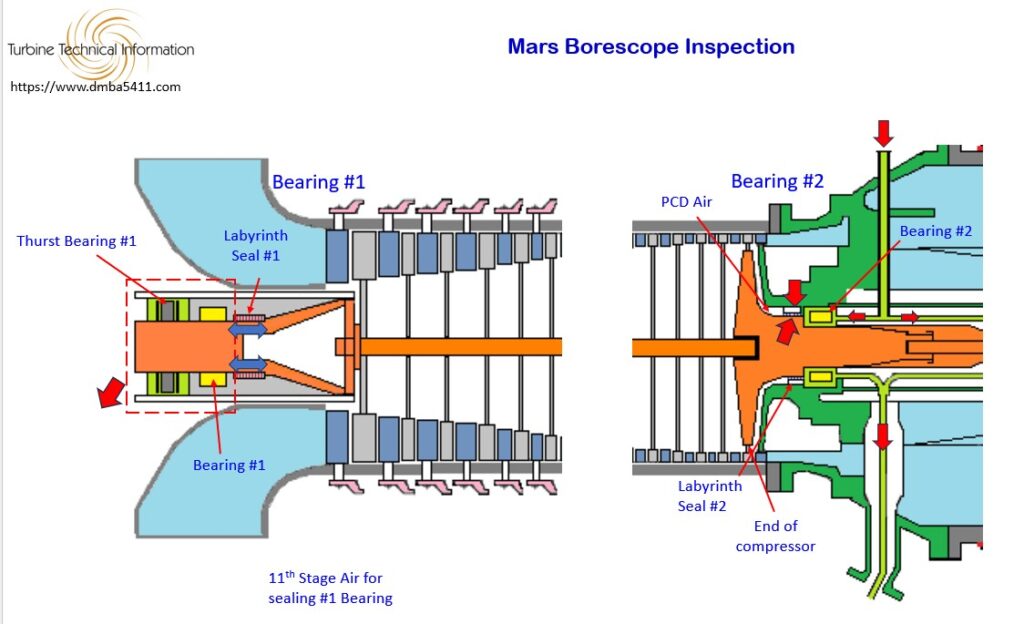
Before we leave the compressor section, let’s take a closer look at oil leaks from number one and two bearing seals.
First lets take a look at number one.
Here we have the thrust bearing for the gas generator, and behind it the number one bearing. And behind the number one bearing we have the labyrenth seal for the number one bearing.
Oil comes into this area here to lubricate the number one tilt pad bearing and the thrust bearing. After it has lubricated both the oil falls by gravity into the Accessory Drive Gearbox and back to the tank.
There is a possibility that the oil could get between the shaft and the labyrenth seal and enter the airflow and contaminate the static vanes and rotating blades.
To help the labyrenth seal we pressurize the seal with 11th stage air. The air flows into the middle of the seal and flows out either end to prevent oil from entering the seal and leaking past it.
Let’s take a look at the number 2 seal.
This is the number two bearing here (point out), you can see the end of the comprssor here (point out). And you have the number two labyrenth seal here (point out).
The lube oil supply comes to the top of the compressor in a flexible hose and then internally via transfer tubes. It then splits into two flows. It goes to the right to number three bearing and to the left to number two bearing.
After the oil is finished lubricating number two bearing it will fall by gravity and flow back directly to the tank. It joins with the oil returning to the tank from number three bearing.
The number two labyrent seal is fitted here between the rotating gas generator shaft and the diffuser casing.
This labyrenth seal is pressurized by PCD air. PCD air being air coming off the last stage of compression.
This prevents any oil leaking out here (point out) and entering into the airflow. Some of this PCD air will flow through the seal and mix with the lubricating oil. They mix together and both flow back to the tank. This is a relatively small flow of PCD air, unless the seal was in poor condition allowing a high flow into the bearing area. This would be seen as a higher than normal lube tank pressure.
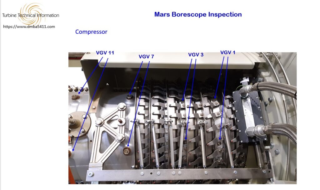
Continuing on with the compressor we see in this photo the compressor casing righ hand side. The compressor casings are split in two, which allows either casing to be removed to gain access to the blades and vanes.
As stated we are looking at the right side of the compressor. Right and left of the turbine is often used to locate components. Front, back, left and right are taken as though you were sitting on the top of the turbine facing the air intake.
The borescope plugs are positioned so that when the borescope is inserted into the turbine, it does not crash with a rotating blade. The access hole will always be at a stator vane.
For this part of the inspection of the compressor you can use a rigid borescope or a flexible fiber optic one. The rigid borescope uses high quality mirrors and a light source. The quality of the view it much better than fiber optics. The rigid borescope is used more commonly on aircraft turbines than on industrial ones.
The flexible borescope gives better movement as you can move around once you are inside the. It also can have various tips depending on whether you need a wide angle, a right angel, straight ahead view etc. There is a big range of tips that can be used. A tip for a combustor inpection for example would need to be a wide angle giving maximum amount of light as it is a large area you are inspecting.
With the flexible borescope you need to be so careful not to get cought up on something.
You can see that there isn’t a borescope access for every stage.
There are sixteen borescope inspection ports in the compressore section. There are four stages with four inpsction ports in each.
As you enter the borescope access hole you can look forward and back. You will see the trailing edge of the rotating blades of the previous compressor and the leading edge of the next compressor stage.
For example when you enter at VGV3 and look forward you you see stage 3 blades and when you look aft you see stage four blades.