
ARTICLE REF – ART011
Alignment shim calculation T60 mobile unit
The following information will serve you on all alignment jobs regardless of the manufacturer. It is very important to have a good understanding of what shims need to be put where when it comes to making an alignment adjustment.

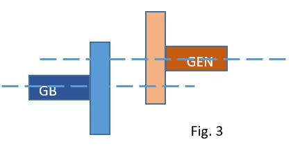
This drawing represents the output shaft of the gearbox “GB” and the generator input shaft “GEN”. The ideal position for these two shafts are to be perfectly in line when all the temperatures have stabilized.
Because this is a cold end drive unit most of the thermal growth will take place at the other end of the turbine (the exhaust end). The centerline should pass through the centers of both shafts when looking vertically and horizontally. On the Taurus 60 cold end drive the gas generator and gearbox combined are considered the fixed maching. This means that any shim adjustment will be done under the generator support feet.

This is a view from above over the coupling. The coupling hubs are not paralell and their center lines don’t superimpose one over the other. To correct this error you need to loosen the hold down bolts for the generator and move it until the centerlines are superimposed. No shim adjustment is need for this kind of error.
This is also a view from above over the coupling. The center-lines are not superimposed. This is corrected by loosening the generator hold down bolts and sliding it to one side until the coupling hubs are parallel and the center-lines are superimposed.

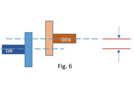
If we have a situation like this when looking from the side of the coiupling, we need to make an adjustment using shims.

If we have a situation like this when looking from the side of the coupling, we need to make an adjustment using shims. The difference between Fig. 4 and Fig. 5 is that the faces are paralell as we want them. So to correction involvs the removal of the same amount of shims from beneath each generator foot. The reality is that we normally have a combination of Fig. 4 and 5.
To correct the problem in Fig. 5 you need to remove an equal amount of shims from each foot to superimpose the center-lines. The measurement is done using dial indicators or laser equipment.

To correct the problem in Fig. 4 you need to do some math. You can use a program to calculate what shims you require, or you can calculate the shims in your head!!!!!!!!!!!
The formula is simple, but you need to see it proved before you have confidence in it.
T60 shim calculation
This is a slightly different example to the one previously (the box is twice as long). It has the same FACE ERROR of (5mm) and you can see that putting 5mm shim at the blue arrow and a 10mm shim at the red arrow will rectify the misalignment. It is no coincidence that the red arrow is two times the distance from the front than the blue arrow and that it needs two times the shim size to make the boxes align.
To calculate the shims at blue arrow ( H / E ) * face error. This is 80mm/80mm * 5 = 5mm of shim.
To calculate the shims at red arrow ( J / E ) * face error. This is 160mm/80mm * 5 = 10mm of shim.
When we do an alignment we make the measurement on the coupling hubs. The blue shading represents a pump for example coupled to a motor. Even though we know the FACE ERROR of the red and blue box is 5mm, there is not a 5mm difference between the measurements taken at the top and bottom of the coupling (it is smaller). To use the formula in the previous diagram we need to measure the distances with a vernier, but for this exercise we will calculate it. Once we have the two dimentions we can calculate the FACE ERROR. .
The left hand side of the red rectangle is offset by 5 mm from top to bottom. Top to bottom is 16 squares. As we move up from the bottom corner the distance to the pump coupling increases by (5mm/16) per square. “G” is four squares up from the corner we get a distance of 3 full squares (15 mm) plus it is up 4 squares (5mm/16)*4 = 1.25 …. Therefore “G” = 16.25 mm.
“F” is twelve squares up from the corner. To calculate the distance “F” ….. 3 squares (15 mm) plus it is up 12 squares therefore (5mm/16)*12 = 3.75 …. Therefore “F” = 18.75 mm.
Shim at blue foot arrow is ( H / E ) * face error …… (80 / 40) * 2.5 equals 5 mm shim.
Shim at red foot is arrow ( J / E ) * face error …… (160 / 40) * 2.5 equals 10 mm shim.
Note – The coupling size “E” was reduced from 80 mm in the previous examples with the boxes to 40 mm in this example. The result of this was that the face error also halved! The diameter where you take the face readings has a proportionate effect on the FACE ERROR. This also proves the formula does work!!!!
To calculate the shim on the front (near) foot:
( H / E ) * face error
( H / E ) is a ratio which does not change as long as you take the readings at the same location every time. In this case it is 80/40 = 2 (I call this the NEAR FOOT RATIO). Once we know the FACE ERROR we multiply it by NEAR FOOT RATIO to get the size shim to install or remove. Note “F” can be greater or smaller than “G”.
To calculate the shim on the aft (far) foot:
( J / E ) * face error
( J / E ) is a ratio which does not change as long as you take the readings at the same location every time. In this case it is 160/40 = 4 (I call this the FAR FOOT RATIO). Once we know the FACE ERROR we multiply it by FAR FOOT RATIO to get the size shim to install or remove. Just as with the near foot “F” can be greater or smaller than “G”.
So let us calculate the Near Foot and Far Foot Ratios for the Taurus 60 mobile unit.
You need to check these three figures are the same on your mechanical installation drawing – just in case there is a different coupling or generator:
Distance generator hub to near foot. …. 24.375 inches
Distance generator hub to far foot. ….. 86.325 inches
Diameter were face reading it taken. .. 9 inches – (if you take the reading closer to the middle you need to compensate in the calculation).
Near foot ratio = (24.375 / 9) = 2.7
Far foot ration = (86.375/9) = 9.6
This takes care of the FACE error.
Let’s try an example where there is just a face error:
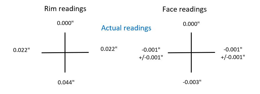
The RIM readings are perfect, but there is a -0.003″ on the Bottom Face that needs to be rectified.
FACE ERROR * Near foot ratio = -0.003″ * 2.7 = -0.008″
FACE ERROR * Far foot ratio = 0.003″ * 9.6 = -0.029
A reading of -0.003″ at the 6-o-clock position means it is too far open at the bottom. You can see that removing the amounts above the bottom will close some.
RIM Error
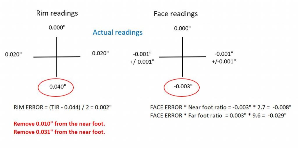
When the RIM readings are not within specification we need to make a correction. In part one of this blog there was a discussion on Total Indicator Reading (TIR). From that we know that any compensation using a TIR reading will mean halving the compensation. Go back and review if necessary as you need to be clear about this. Let us look at an example where the FACE readings of the T60 were perfect so the only compensation will be to the RIM reading.

The actual reading for the bottom rim (what Solar call Bottom Bore) is +0.040″ which means the gearbox is lower than the generator, which is correct. But the DTI needs to be reading 0.044″ to be perfectly in specification. Even though it is actually within the tolerance, we are going to make a compensation for this exercise to bring it perfectly to 0.044″. The RIM ERROR is = -0.002″, (half the TIR ERROR ~ Actual reading – Required reading).
We know the FACE is reading perfectly so whatever shim change we do make, we to do it equally on all the generator bolt down locations.
So if we remove 0.002″ from each generator bolt down location the alignment RIM reading should be 0.044″. As stated earlier this was already in spec so we would not be adjusting it by 0.002″.
Calculate shims when there is a combination of FACE and RIM errors.
(FACE ERROR * Near foot ratio) + RIM ERROR is the shim compensation for the near feet.
(FACE ERROR * Far foot ratio) + RIM ERROR is the shim compensation for the far feet.
EXAMPLE
If you were to do this calculation in your head.
RIM error is -0.002″ ~ it is negative because is less than spec 0.044″.
FACE ~ for the face round the ratios ~ Near foot 3 …. Far foot 10
For the last example you would get -0.011″ for Near foot and -0.032″ for the Far foot. That is close enough to get you into spec!