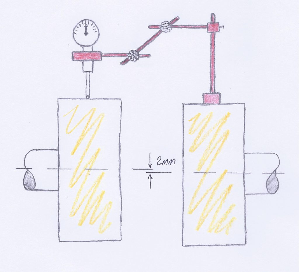
The dial test indicator (DTI) is zeroed at the 12-o-clock position. The shaft on the right is turned 180 degrees until the DTI is at the bottom of the coupling hub on the left.
What will the DTI be reading?
A ….. 0mm D ….. -2mm
B ….. 2mm E ….. -4mm
C ….. 4mm
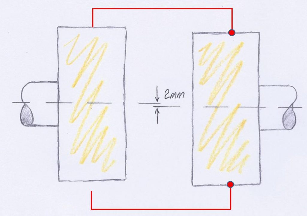
The DTI was replaced with a piece of wire which was fixed at the red dot. It was positioned so it just touched the coupling hub at the 12-o-clock position. Then it is shown at the 6-o-clock position and you can see there is a gap. That gap will be 4mm.
Rule number one.
If you are going to use a DTI to read the height of one shaft with reference to the other you are going to be reading double. This is called Total Indicator Reading. The compensation you would use to align both shafts is 2mm.
rule number two.
In the last diagram above there is a gap of 4mm between the tip of the wire and the bottom of the coupling hub. If there was a DTI instead of a piece of wire it would extend until the stylus would touch the shaft. If the stylus of a DTI extends the reading starts to go in the negative direction. The answer therefore to the original question is ………. -4mm.
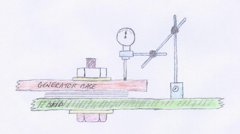
Soft foot.
The generator of the T60 is several tons and presses down on each mounting foot with all its weight. The generator sits on top of a skid which hopefully is installed with all the mounting surfaces on the same vertical plane. This would be one of the items checked during the build of the T60 structure. If the support skid was twisted it would cause the mounting pads to be on different vertical planes (levels). This situation will cause what is called “soft foot”. To check for soft foot torque all the generator mounting bolts to ensure all are bolted down equally. Then attach a magnetic base with a DTI as indicated in the sketch above. Zero the DTI and then loosen the mounting nut and observe how much the generator base will rise. It is normal for the base to rise a couple of thousands of an inch, and this is ok. You need to check all the mounting bolts, one at a time, torquing the same nut once it is checked before checking the next one. Soft foot need to be eliminated at the start of the alignment job. If one foot springs up more than the rest you should investigate. If you don’t find anything that you can correct, then you need to insert a shim of equal size as what was indicated by the DTI. Then recheck the value again to ensure it is similar to all the rest.
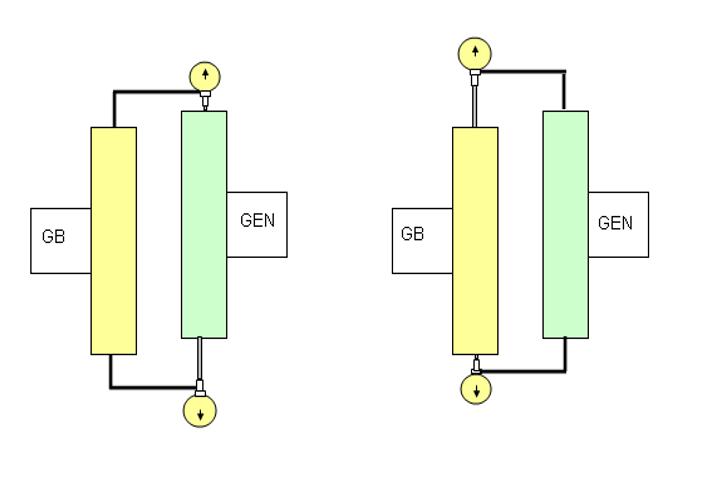
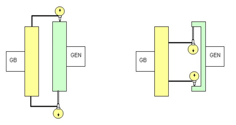
Changing target side
The Solar drawing for the T60 alignment shows the tooling attached to the generator hub. This means that you have to turn the generator to take the readings. If you look at the sketch on the left it shows the alignment tooling mounted on both sides. This is done to show the effect of doing such a thing.
The left hand side sketch has the tool is mounted on the gearbox and is reading the generator. This is the opposite to what is required by Solar on the T60 mobile unit. If you zero the DTI at 12-o-clock and move to the 6-o-clock position the DTI stylus will extend which means it will go negative. The right hand sketch has the tool mounted as is the case with the T60 mobile unit. Set zero at 12-o-clock and as the DTI is turned it starts to go positive and the stylus compresses. The amount the DTI will go negative or positive is the same figure but has different signs +/-.
The Titan 130 alignment setup is similar to the T60. It has a very heavy generator rotor which is difficult to turn. Because of this technicians often mount the tools on the gearbox and read the generator. If you do this you need to know what you are doing and also know the values will change sign.
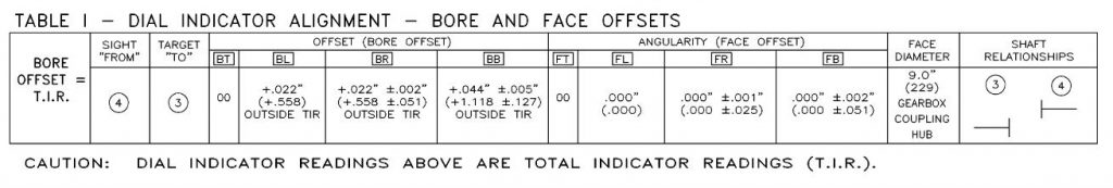
Bore and rim readings
The left sketch is a RIM reading, the right sketch is a BORE reading. For some reason Solar calls both of readings BORE readings. Of late they have used the words Outside “TIR”.
The readings will be opposite sign so you need to use the correct one. If you see Outside TIR it is a RIM reading, just ignore the word BORE. So the T60 mobile unit is a RIM reading and the reading at 6-o-clock position is +0.044″
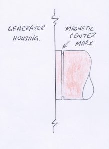
Magnetic center
The generator rotor is supported by two white-metal bearings and is free to move axially. During transportation of the unit there is a frame fitted to lock the rotor so it can’t move. When the generator is excited and the breaker is closed the rotor and stator will go into a magnetic lock taking up a particular axial position called “Magnetic Center”. It is important during alignment that the generator be positioned the correct distance from the gearbox because if it is not then there will be axial forces on the coupling which can cause high vibration and coupling failure.
The sketch on the left shows a machined line on a generator shaft. The maintenance manual states ” Position generator shaft to magnetic center by shifting generator shaft axially to align shaft with vertical face of generator housing”. Once the generator rotor is in the magnetic center position you can read the distance between hubs to ensure you have the correct gap (generator is in the correct position).
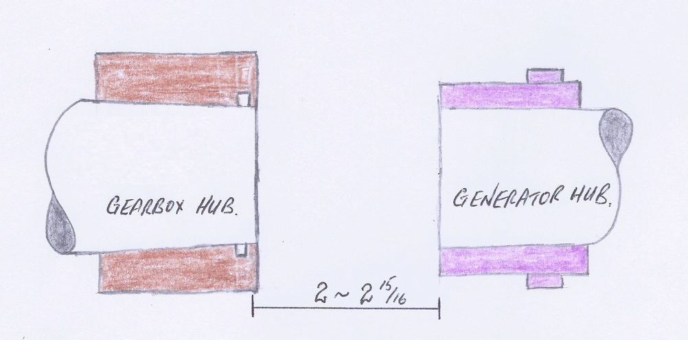
Hub to hub distance
Check the Mechanical Installation drawing to see what the axial dimension is and to see where it is measured from. Couplings change from time to time and may not all be the same on every project. This dimension has to be within specification just as the FACE and the RIM reading. Once these 3 readings are withing spec the alignment is good.
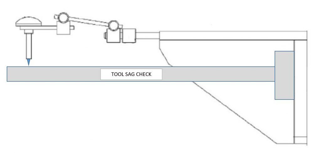
Tool sag check.
To check the sag of the tool you need to mount the tool on some solid structure which will not flex in any direction. Set the DTI to touch the structure and then zero the DTI. Rotate the alignment tool and sag check tool so the stylus is pointing vertical upwards. If the alignment tool is bending under its own weight the DTI will register a positive reading.