
ARTICLE REF – ART216
This article is going to discuss the set up to inject a vibration signal to simulate an alarm or shutdown, on a Solar turbine using Solar’s Field Tool FT51010-13.
There are three types of transducers used on vibration systems to measure vibration.
- Displacement
- Velocity
- Acclerometer
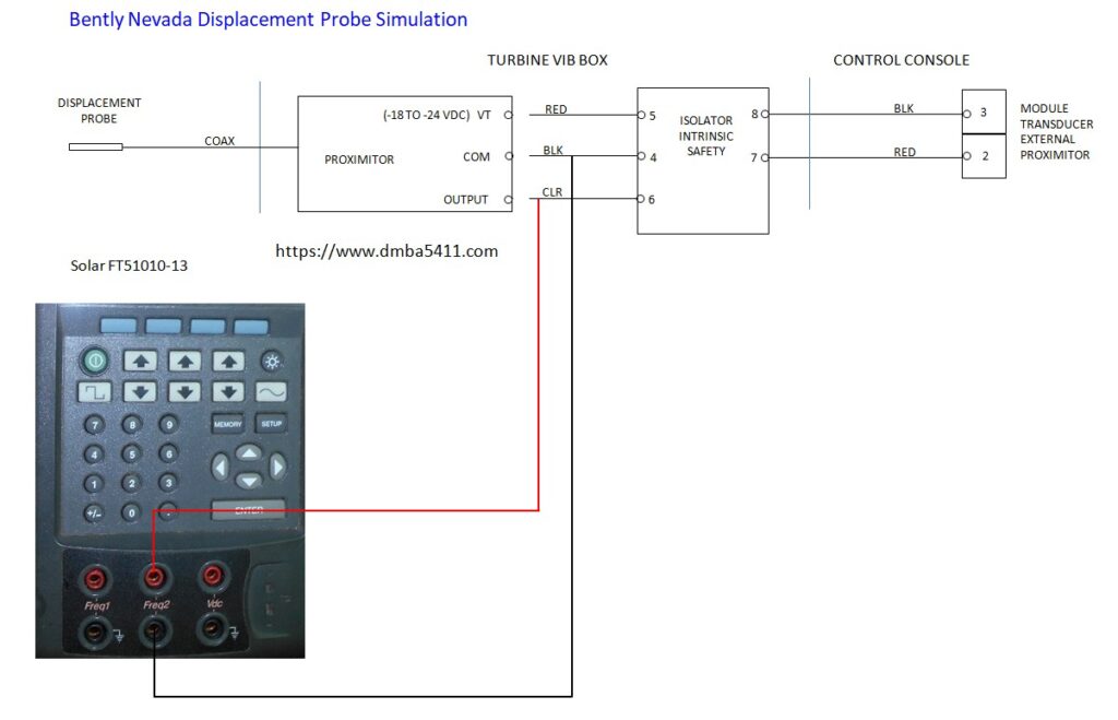
What we are going to discuss here is the Displacement transducer, often called a Proximiter. The probe is connected to the Proximiter using a coaxial cable of a specific electrical length. If the cable ever needs to be replaced, it needs to be the same part number. The proximiter is an electronic box that generates a high frequency signal that is sent to the tip of the probe, where it excites a coil of very fine wire at the tip of the probe. This signal sets up a magnetic field around the tip of the probe which induces a magentic field in the shaft that it is reading. This creates Eddy Currents that effect the returning signal to the Proximiter box. We need to inject a signal after the Proximiter box, to simulate the signal that it sends to the vibration monitor.
The signal has two components, a DC and an AC part. The AC signal is superimposed on top of the DC signal. The Solar Field Tool FT51010-13 is capable of producing this type of signal. This signal can be reproduced by a standard frequency generator, but using this tool makes it very simple.
All Solar displacement vibration limits are given in Peak to Peak. This is important when you input the amplitude of the signal. Let’s look at an example of simulating an alarm with a set point of 4 mills Peak to Peak. The sensitivity of the displacement probe used by Solar / Bently is 200 millivolts per mil (mil being one thousand of an inch). To get the frequency generator Field Tool to generate this amplitude, it needs to be set to (200 * 4 = 0.800 Volts. If the alarm set point was 4 mils Peak, you would only need to inject an amplitude of 0.400 millivolts.
In the drawing of the vibration channel above you see that there is a Barrier. These barriers are normally used but some Solar customers don’t use them. The purpose of hte barrier is to divert to ground any dangerous currents that might be fed from the control system to the probe and cause a spark. Intrinsically safe barriers will reduce sensitivity to 192mV/mil if installed. This means if you inject 800 millivolts, you can expect to only get 768 millivolts or 3.84 mils of vibration on the display. You would need to 843 millivolts to get 4 mils vibration displayed.
Connect the test leads to either of the two channels of the frequency generator. Connect the end of the test leads to the wires leaving the Proximiter (we will not be injecting through the p1roximeter). Note that frequency signals are polarity sensitive, so if this procedure does not work for you, try reversing the leads. Set up the following parameters on the frequency generator.
- Select Channel
- Input the frequency in hertz – normal running speed of shaft in hertz
- Input the AC voltage P-P you want to inject – “we calculated 843 mV”
- Input the voltage Bias “-10 volts DC” – this is the DC voltage that the AC signal rides on.
- Select the waveform “Sine Wave”
Go to the display and you should see a vibration amplitude of 4 mils. If the alarm is not being annunciated, increase the amplitued in small amounts until it activates. If the alarm is activated, note the value and move to the next channel to continue testing.
End of article.