
ARTICLE REF – ART228
Lube System Control and Alarms
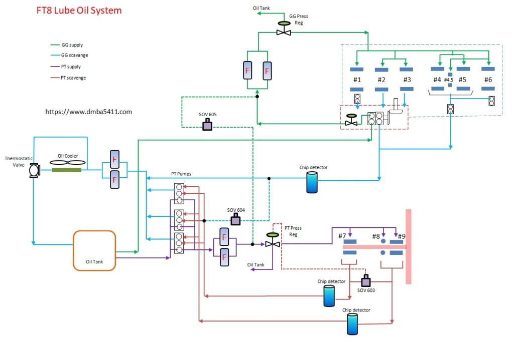
This is Part 1 of Control & Alarms of the Lube Oil System. Let’s look at oil tank which is one of the items shared by both Gas Generator and Power Turbine lube systems.
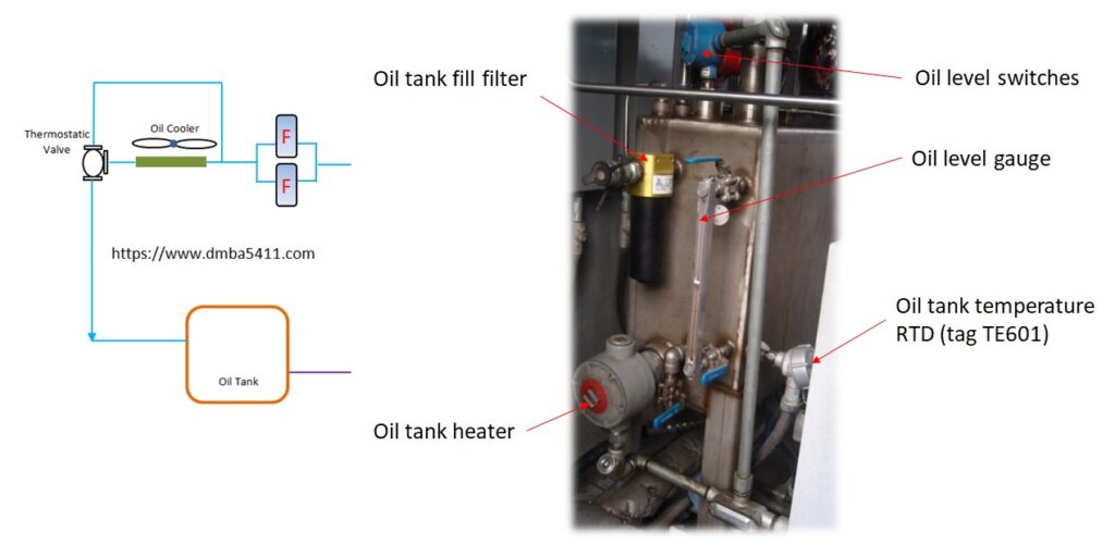
This is a photo of one side of the oil tank.
- Coming out of the top of the tank are the two level switches. These are two discrete input electrical loops to the control system.
- There is a sight gauge to phyfically see the oil tank level.
- Coming out of the front of the oil tank is the oil tank Resistive Temperature Detector which measures the oil tank temperature and is an input to the control system.
- On the bottom side you see the oil tank heater.
- Lastly the oil tank fill filter. There is a quick connect connection to an external hose for topping up.
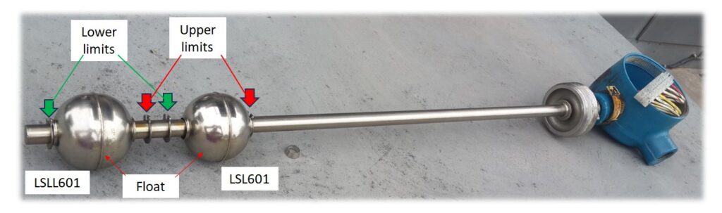
This photo shows the level switch assembly which is screwed into the top of the lube oil tank.
There are two floats mounted on a hollow shaft which cause reed switches to operate when the float is in line with the reed switch. These switches change state as the oil level drops. Circlips limit the movement of each switch. Both floats will be at the upper limit when in normal service. As the level drops the upper float, which activates level switch LSL601 will CLOSE the circuit when at the low level position.
As the level continues to drop the lower float will activate at the lower end of its travel to OPEN the level switch LSLL601. The level of oil in the tank will be 7 inches at this time. Use of the starter is not available until the tank is topped up.
Note that one circuit opens while the other closes its circuit.
The capacity of the tank is only 140 liters, which is not a lot of oil. Keep this in mind if you have oil leaks. The oil used is Mobil Jet 254.
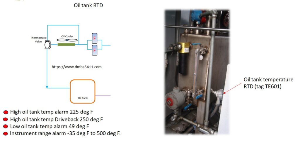
The next instrument we will look at is the oil tank temperature RTD – tag TE601. There are two RTDs, one is connected to the control system and the other is a reserve. This means you don’t have to drain the oil tank to replace an RTD if one fails.
High temperature alarm is set at 225 degrees Fahrenheit and clears when it drops below 224 degrees.
If the temperature reaches 250 degrees Fahrenheit there is a “Drive Back”. The power on the unit is reduced in an attempt to reduce the oil temperature. The drive back can be reset at 240 degrees.
If the oil temperature drops to 49 degrees Fahrenheit there is an alarm for low lube oil tank temperature. No starter rotation is allowed on the turbine, so not windmilling, and no start or spin. It is in effect a “Start Permissive”. This alarm clears at 50 degrees. To prevent the oil temperature from dropping the oil tank heater is commanded on.
The RTD has a signal fail alarm if the temperature goes outside the limits of -35 degrees to 500 degrees Fahrenheit.
Next let’s look at the Oil Tank Heater, which ensures the oil is kept warm when the unit is not running. In hot climates this heater may not be needed. The oil system is designed to keep the oil temperature within a certain range, to ensure the viscosity of the oil is optimum for lubricating and cooling.
While the turbine is in service there isn’t a need to heat the oil, the need is only when on standby.
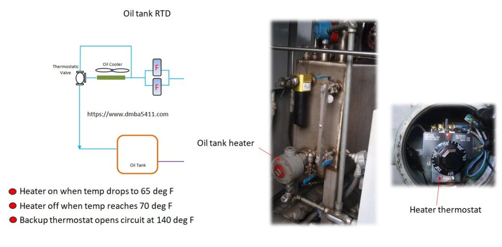
The Oil Tank RTD is used to command the heater on / off. The heater is commanded on when the temperature of the oil drops to 65 degrees F, and is commanded off when the temperature reaches 70 degrees F.
This is a 1.5 kW heater and apart from the control system switching it on and off there is a backup thermostatic switch which will cut the current to the heater at 140 degrees F. The cutting of energy to the heater is independent of the control system. It is an extra safety, just in case the control system stopped working.
End of article