
ARTICLE REF – ART230
The FT8 is derived from the JT8D aircraft turbine. It has an additional two compressor stages added to the front of the existing JT8D. This gives additional power to the FT8, but in doing so the turbine produces more heat. This additional heat was a problem for bearings 4, 5 and 6 as the oil in these bearings started to produce coke.
Coke is formed when oil is overheated and produces a hard substance which causes wear on bearings, pumps, valves, and blocks filters, orifices etc.
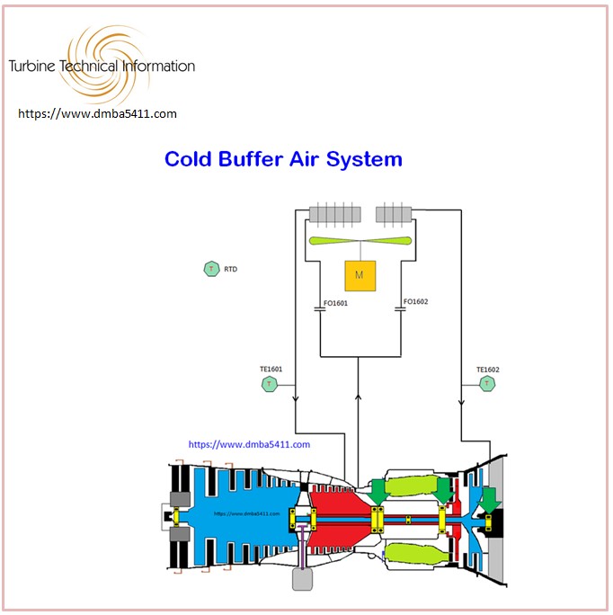
The Buffer Air System was introduced to combat this overheating of the bearings, by delivering relatively cooler air to these bearing areas to cool them.
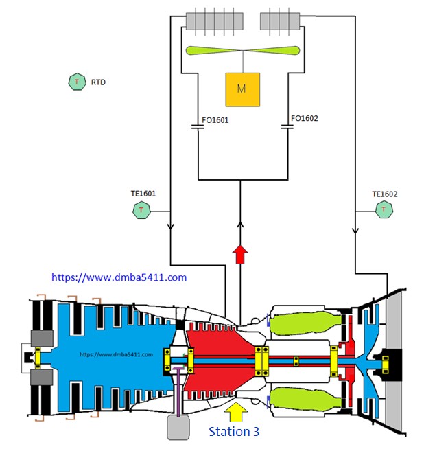
Air it taken from the last stage of compression, called P3 air. Standard “turbine position locations” are used by all turbine manufacturers. Station 3 is where the last stage of compressor is located. The air temperature at this station is called T3 air, and the pressure at this location is P3 air pressure.
This air is at least 260 PSI and in excess of 400 degrees F.
These are dangerous pressures and temperatures to be working with, therefore care is needed to ensure safety at all times.
The reason for using the hot air to cool the bearings, is to prevent “Thermal Shock” to the bearing metals. Air at low temperatures could damage the bearing metal structure, and caue failure of the bearings.
Three flexible Cold Buller Air hoses are attached to the turbine. One is the flow of 13 stage air supplying the CAB with cooling air. Physically this is actually 15th stage air as two additional stages were added on to the front of the turbine, but the naming convention never changed with the new design.
The air is taken from the diffuser casing, as this is where the maximum air pressure is found on the turbine. Note there isn’t a valve or solenoid to to control the flow of air.
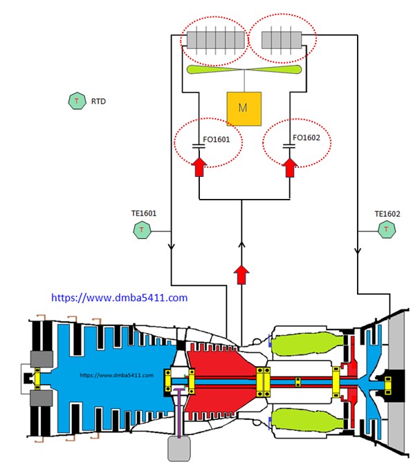
The air then splits into two flows, just before passing through a flow orifice (FO1601 & FO1602) in each line. These orifices are important to help determine the flow of air through the cooler. The lower the flow, the more cooling the air will recieve.
These orifices are checked annually to ensure the flow and therefore cooling of the air is being performed correctly. We will discuss that maintenance check later.
The flow to the right hand side flows through a cooler, smaller than the other. This is another factor effecting the temperature of the returning air.
The flow on the left hand side flows through its cooler, and both are cooled with a single mortor driven air fan. Note that the not only are the coolers different sizes, the orifices are also different diameters.
Another factor controlling the Buffer Air temperature, is the speed of the cooling motor. It is driven by a Variable Frequency Drive, and therefore can vary its speed.
There is only one fan cooling two air heat exchangers, but the control system can only speed up or slow down to control one of the temperatures.
It is the temperature for bearings 4&5 that is controlled. The control system reads the temperature of RTD TE1601, and uses it to determine the error between the current temperature and the setpoint of 350 degrees Fahrenheit. The control of the Buffer Air to bearings 4&5 is more critical and for this reason it was chosen.
During the design of the system the engineers sized the cooler, orifice etc, to ensure that when the temperature of 4&5 was being satisfied there would also be correct cooling for bearing 6. But at times the air temperature to bearing 6 will be outside limits and this is addressed during the annual maintenance. More on that later.
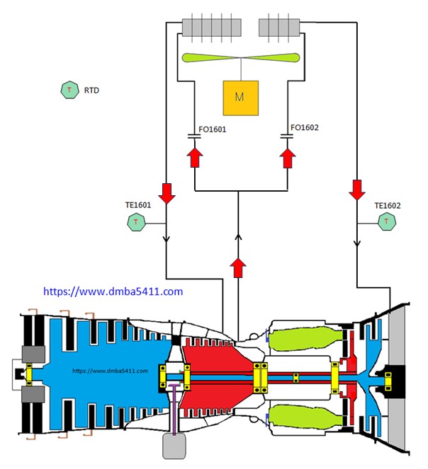
The cooled air now flows past the RTDs which are used for control, alarms and display. The air then flows into the turbine throug passages etc to the bearing areas to cool them.
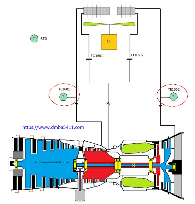
RTD TE1601 measures the cooled returning air on its way to bearings 4&5.
If the temperatur is in excess of 365 F there will be an alarm and at 380 there will be a driveback.
RTD TE1602 measured the cooleing air for bearing 6.
If the temperatur is in excess of 250 F there will be an alarm and at 275 there will be a driveback.
Note that these are all high air temperature alarms – the cooling air is too hot and needs more cooling.
Now we need to look at protection of bearings should the cooling air be “too cool”.
We have alarms for these too. The unusual thing about these alarms are that the value of the alarm is not fixed. Nor is the value read into the control by an RTD. Instead a calculated value called “T3 Synthesis” is used.
The following instruments and logic are used in the controller.
PT007 – Combustor pressure.
PT006 – Air intake pressure.
TE010 – Air intake temperature.
Logic – uses Bleed Valve postion – open or closed as a bias in the calculation.
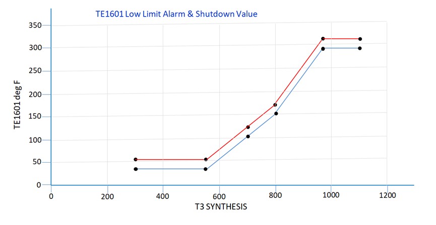
With reference to the Alarm / Shutdown slopes in the diagram above, the red line is the alarm and the controlled shutdown is the blue line which is 20 degrees cooler.
The red control slope is for the alarms for bearings 4&5. Bearing 6 has a seperate control line.
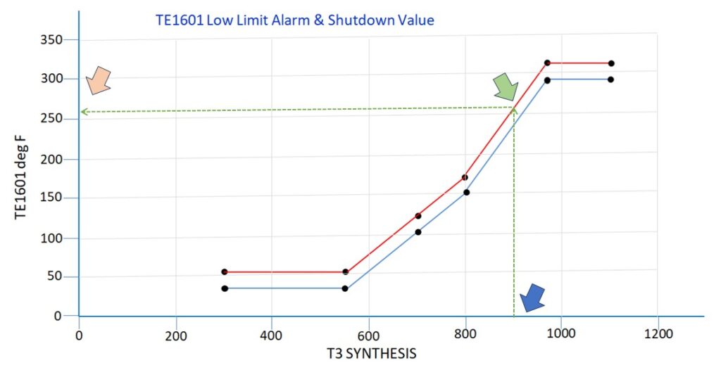
Use the graph as follows.
Locate the calculated “T3 Synthesis” on the X axis (blue arrow).
Follow that point vertically until it intersects the Alarm or Shutdown slope – in this example it is the alarm slope (green arrow).
Then move from the intersection point, horizontally to the Y axis.
The Y axis value is the current “T3 Synthesis Alarm” value, that will be used by the control for alarm.
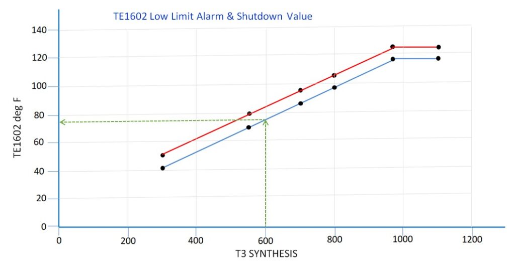
The graphic above shows the Alarm and Shutdown slopes for TE1602 or bearing 6.
Note the green dotted line repesents the current shutdown value for TE1602. The alarm is 20 degrees higher.
All the previous alarms / CDB / CSD are disabled if:
NH Reference is increasing
NP Reference is increasing
NH Speed is increasing by at least 50 RPM / Sec
Once the above preventions have cleared, two minues must pass before they become active again.
A failed RTD sensor will disable the alarms for that sensor.
If both RTD sensors are failed there is a Controlled Shutdown.
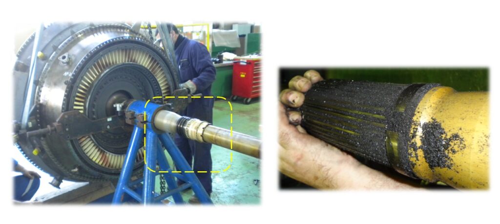
The photo on the right above is the end of the LP Turbine shaft where it joins the LP compressor. This is what coke looks like. In this example it is due to a failed four and a half seal. There was much more coke in the cavity where the shaft was removed.
The photo on the left is the LP shaft and LP turbine removed from the rest of the turbine. The yellow rectangle is the four and a half bearing and seal.
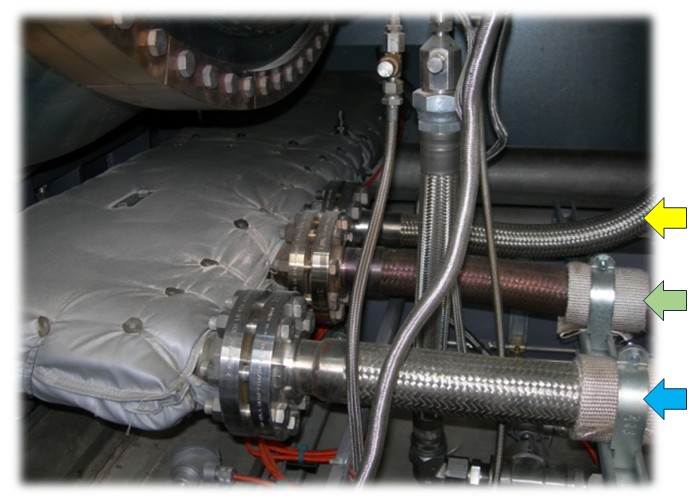
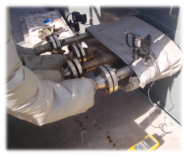
Above is a photo inside the enclosure, under the turbine, where the three cold air buffer air pipes run before being connected to the underside of the turbine.
Notice the colour of the 13 th stage air hose (green arrow), discoloured by the heat of the compressor discharge air.
The hose going to bearing 4 / 5 (blue arrow) is larger than the one going to bearing 6 (yellow arrow).
The 13th stage air is in the middle and splits to go to each cooler individually.
After passing through each cooler the two lines return to the bearing areas to cool them.
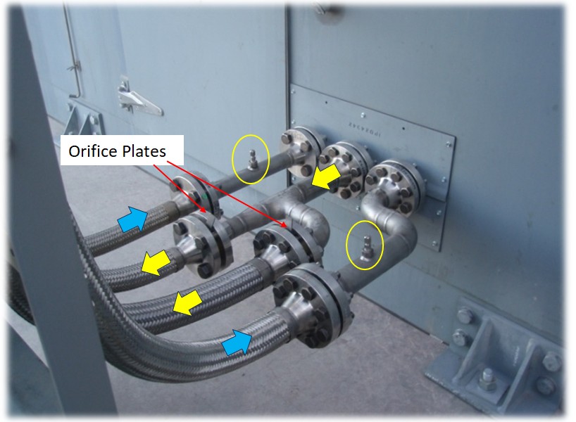
In each supply line there is an individual orifice plate.
The 2 inch line to bearing 4/5 has a 0.880 inch diameter hole for FT8-1 installations and 0.821 inch diameter for FT8-3 installations.
The 1-1/2-inch pipe to bearing #6 has a 0.320 inch diameter hole for FT8-1 installations and 0.328 inch diameter for FT8-3 installations.
These are the sizes used during commissioning, but they may change with time. A box of different orifice sizes is shipped with new equipment for this reason.
These two locations are where the pressure gauges are mounted for the annual maintenance check. More on that later.
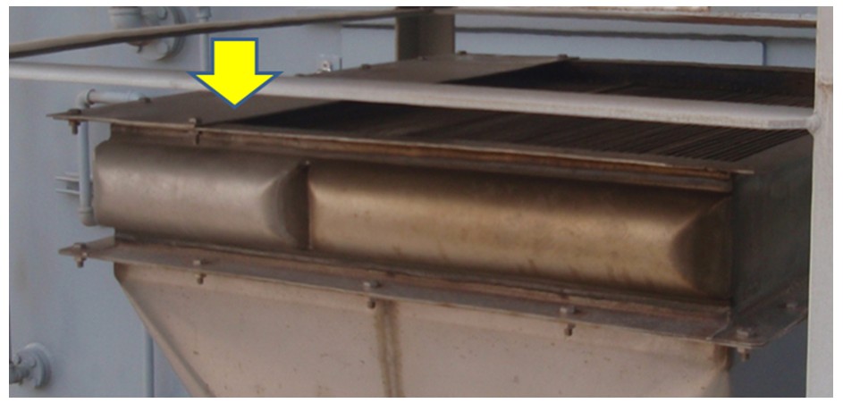
This photo above shows the heat exchangers. The small heat exchanger is for bearing 6.
When you calibrate the CAB by verifying the orifice size, you can still run into problems. The VFD should be able to control the air for 4&5 by varying the speed of the VFD. But you may get some alarms for the cooling air for bearing 6. If this happens you will first make any orifice changes recommended. And if you still need to make an adjustment you may need to adjust the sheet metal position installed on the top of the small heat exchanger to adjust the amount of cooling.
NOTE – this sheet metal is not fitted on the FT8-1
CAB P&ID
As well as the drawing showing a detailed layout of the piping and instrumentation, it gives you all the tags which are an important starting point for troubleshooting.
A lot of the system items have PWPS part numbers not found anywhere else.
Also instrument ranges and alarm settings.
Annual Maintenance Check
Install a 0 to 100 PSI gauge or in this example a calibration transducer on the # 6 bearing return line.
Install a 0 to 300 gauge on the #4/5 return line.
All pressure readings must be converted to PSIA for calculation.
Next run the turbine at Base Load
Note the returning pressure to bearings #6 and bearings #4/5
Calculation for bearing #6
Returning pressure from cooler to bearing #6 (PSIA), divided by
PT007 Burner Pressure (PSIA)
The result must be 0.320 +/- 0.02
Change orifice plate size if need be to get the pressure ratio withing specification.
Calculation for bearing #4&5
Returning pressure from cooler to bearing #4/5 (PSIA), divided by
PT007 Burner Pressure (PSIA)
The result must be 0.845 +/- 0.02
Change orifice plate size if need be to get the pressure ratio withing specification.
As stated earlier the cooler motor is controlled by a Variable Frequency Drive. A 4 to 20 milliamp signal from the control system to the VFD determines the speed set point.
The CPU logic is controlling the speed to keep the temperature of TE1601 at 350 Fahrenheit. The speed of the VFD will be ramped up in speed to decrease the temperature and ramped down in speed to bring up the temperature of TE1601.
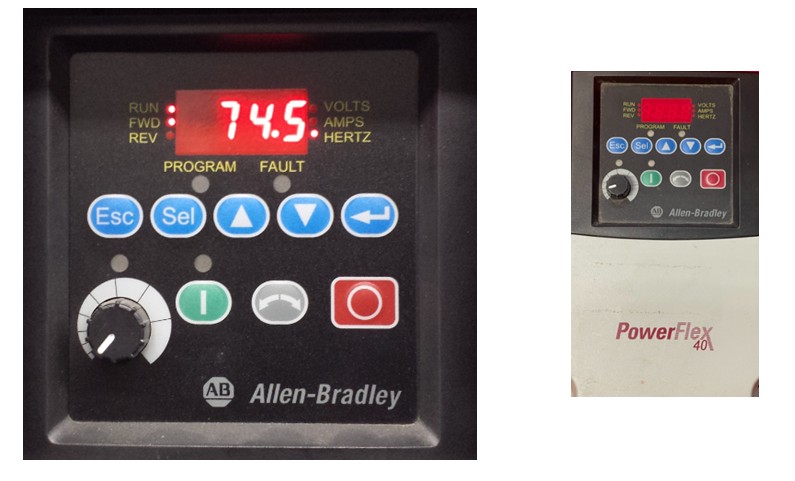
The most common model in service now is the Allen Bradley PowerFlex 4.
It has a local display which by default shows the current output frequency
The following information discusses how to navigate to the different parameters. This will be very important when troubleshooting.
Normally the output frequency in Hz is displayed. In this example it is 74.5 Hz.
If the Hz value is not being displayed – keep pressing the “Esc” button until you do see it. This is called “Display Parameter D002”
From here press “Sel button” and “d002” will continue to be displayed but with the “d” flashing.
If you press the “Arrow up or Arrow down” you will cycle through the different parameter tyes available ie.
D – display group
P – basic program group
A – Advanced group.
If you want to accept “d” then press “Sel” and the curser will move over to the parameter number and start flashing. You can move up and down the parameters until you get to the one you want, then press the “Sel” button.
Once the parameter value is changed to the value you wish, press the “Enter button – (arrow left) to save the new value.
It is important that parameter P034 is set to 5 and parameter P035 is set to 74 as these become the minimum and maximum frequency for the 4 and 20 milliamp signals.
See TPMD416 for reference.
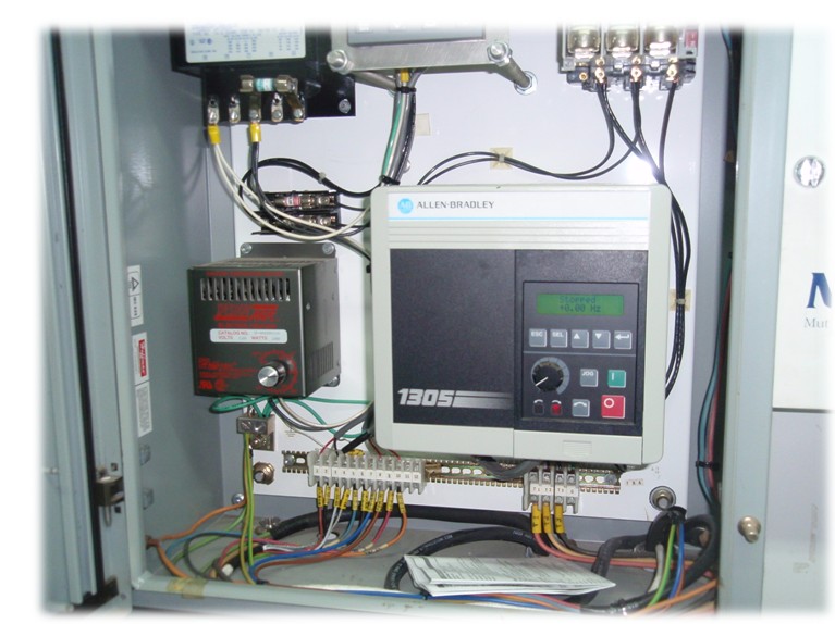
The photo above is the older VFD from Allen Bradley, model 1305 which you still see on some units. It is no longer supported by PWPS.