Training and Troubleshooting documentation and videos.
ART246 – FT8 – How to locate “Tunables Tags” in Control Assistant
Article Reference – ART246
FT8 instruments don’t have “Zero” and “Span” calibration adjustments, therefore the adjustment is done in the control software called “GAP”. This article is going to describe how to locate the adjustment addresses called “TUNABLES”, so that you can calibrate the control signal.
The FT8 Electrical Schematic Drawings and GAP Logic, have all the inputs and output channels in the order you find them on the RACK – CARD – CHANNEL, starting with Rack 1, Card 1, Channel 1, and continues to the last Channel, in the last Card, in the last Rack.
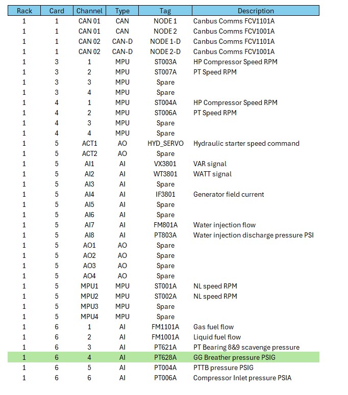
There isn’t an index of instruments, as you normally find on schematic drawings, to indicate the drawing page number where the instrument is located. Therefore you need to start with the “Input / Output List”. This is a drawing (list of all the inputs and outputs that enter the control system) which can be found in the “Project Documents”. The following information is what to expect in the I/O List. This is a “Mobile Pac” (yours may be different).
I am going to use Pressure Transmitter PT628 as an example in this article. You can see it is located in Rack 1, Card 6, Channel 4.
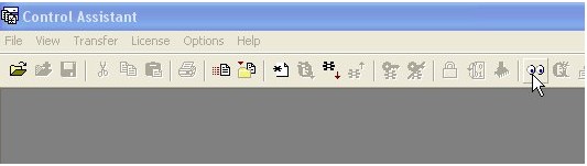
Once Control Assistant is open, you need to click on the “Two Eye” icon indicated by the curser.
If a connection was previously established with the CPU, you can accept the default values and select “Connect”. If this is the first connection you need to set up the communications with the correct protocol. This will not be discussed here.
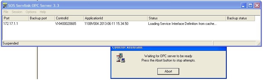
The graphic below shows Control Assistant trying to establish communications using “OPC Servlink Server” (which is like a software driver) trying to make the connection to the CPU. It is trying to connect to “Port” IP Address 172.17.1.1. The Control ID which is VXM00020665 is the CPU identification tag. This ensures you are connecting to the correct CPU (as there may be more than one turbine on the network).
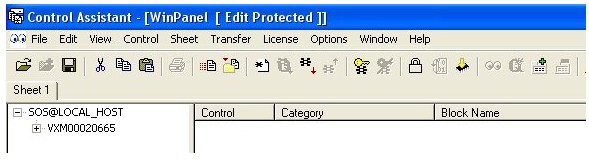
What you should now see, the processor name – in this example VXM00020665.
Clicking on the + will show the complete list of categories.
Remember where the transmitter PT628 was located in the “Rack – Card – Channel” ………. (1-6-4).
So go down until you find the Category A1_A06_AIO. This corresponds to the card which contains PT628.
Double click on the “+” at A1_A06_AIO and there are a lot of entries under this. These are called Blocks. There will be many blocks including a block for every instrument that enters or exits this card 1-6-4.
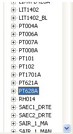
Down towards the bottom of the list you will find PT628.
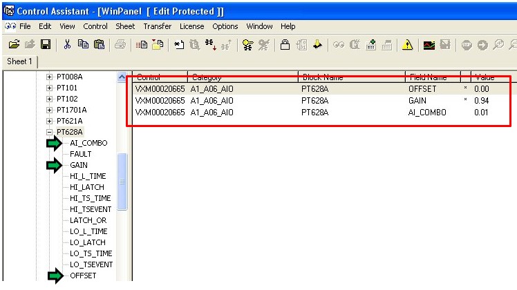
Now double click on “+” to see a list of all the inputs and outputs to this block.
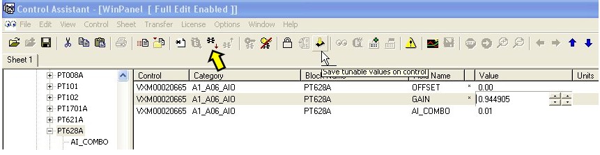
Now drag the two tunables and the output value in PSIA, to the right hand side of the screen as shown below. You will see the effect of any changes in the Output Value while tuning the Gain and Offset.
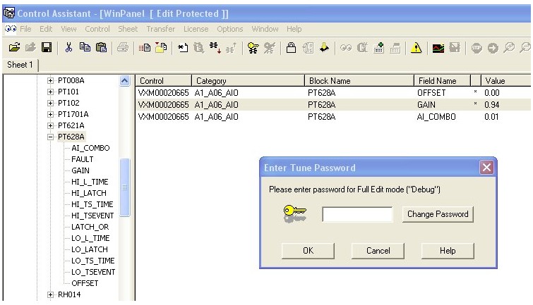
When you attempt to change any of the tunables you will be asked for the password, it is “1112”.
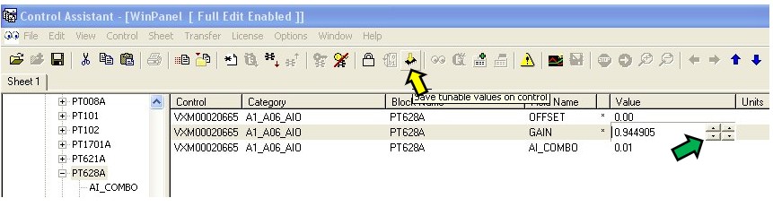
Once the change has been made using the up and down arrows (green arrow), you will have to save the changes to the control (non volatile memory). You can do this by clicking on the yellow arrow pointing down at the chip.
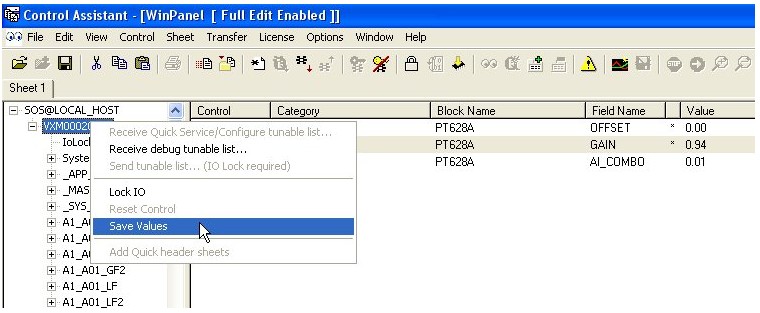
Another way to save the changes is to select the processor name and then right click and select Save Values. Should someone reboot the CPU the changes you made will be loaded.
You should also save a copy of the Tunables on the hard drive of the display. To do this click on the icon indicated by the yellow arrow and you will download the Tunable File to save where you wish.
This method of selecting tags can also be used in Control Assistant “TREND VIEW” to collect live data of “ANY GAP TAG” – not only analog values ……… Very powerful for troubleshooting.